Self-Driving Cars: The Guide
The previous century was marked by the arrival of the car that completely transformed our society. Cities were built to integrate cars. A cult is born. For over 100 years, thousands of businesses have sprung up around the car, from transportation to fast food on the highway. The car is an everyday object that has become essential to our lives. However, this unavoidable tool has become one of the leading causes of death in the world and a particularly polluting object in big cities.
Autonomous cars (driverless) eliminate the human error responsible for the majority of accidents and switch to a mode of electrical consumption that does not reject fine particles. In recent years, more and more companies and manufacturers have decided to invest in driverless systems. Simple trend or real disruption of our lifestyle? The question is no longer there. In the age of artificial intelligence, big data and robotics, the autonomous car is more than ever at the heart of today’s innovation to transform our future.
This article concludes the series on self-driving cars :
- Introduction to Computer Vision for Self-Driving Cars
- Sensor Fusion - LiDARs & RADARs in Self-Driving Cars
- Self-Driving Cars & Localization
- Path Planning for Self-Driving Cars
- The Final Step : Control Command for Self-Driving Cars
If you want to have a perfect understanding of self-driving cars, I highly recommend reading the articles that go deep inside every part of what makes a car autonomous.
Through these articles, we discussed the different bricks that make a car autonomous :

- PERCEPTION — This step makes it possible to merge several different sensors (camera, LiDAR, RADAR, …) to know where the road is and what is the state (type, position, speed) of each obstacle. This defines an understanding of the world in which our car drives.
- LOCALIZATION —This step uses very specific maps (HD Maps) as well as sensors (GPS, camera, LiDAR, …) to understand where the car is in its environment at centimeter level.
- PLANNING — This step uses the knowledge of the car’s position and obstacles to plan routes to a destination. The application of the law is coded here and the algorithms define waypoints. This makes decisions and guides the vehicle to a destination.
- CONTROL —Taking into account the road and the vehicle, and integrating physics, we develop algorithms to follow the waypoints efficiently. This moves the vehicule by operating the brake, acceleration and steering wheel.
In this last article of this introduction to autonomous vehicles, we will discuss the integration of all these steps in a real car. We will also see a real self-driving car architecture. But before that, let's begin with a little bit of Hardware!
Before we start, if you haven’t downloaded it yet, I invite you to join the emails and receive your Self_Driving Car MindMap to read this article with a great understanding and an overview of self-driving cars.
What does an autonomous car look like?
An autonomous car looks like any car except that sensors and computers are added to allow self-driving navigation.
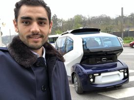
What cars ?
All cars can not be made autonomous. A car is controlled by the Control step, responsible for generating three values:
- The steering angle
- The acceleration value
- The brake value
To be autonomous, a car must be able to give electronic access to these three values. In old cars, these values can only be changed manually (by turning the steering wheel, for example). In recent cars it is possible to take control of the steering wheel and pedals with buttons.
These cars are called Drive-By-Wire cars.
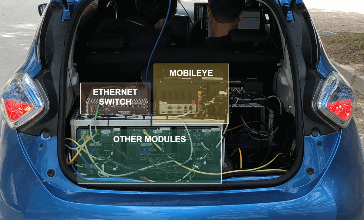
The trunk
The majority of autonomous cars have a trunk similar to this one. Computers are connected to each other and to the sensors of the vehicle. Some modules can be sold by companies that provide a “black box” computer that connects to the main computer and sends CAN messages.
The roof
Depending on the choice of the manufacturers, an autonomous car can have LiDARs and cameras on its roof, in the front, in the back and look like that.
They all do not make this choice and some prefer the design.
Connectivity
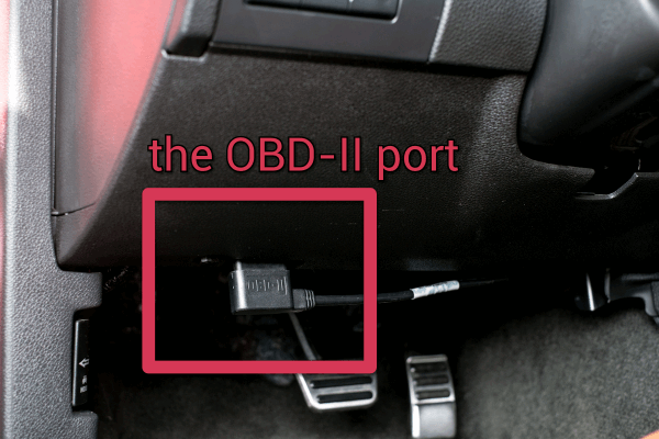
To connect the trunk computers to the car, we plug the mainframe into the vehicle’s OBD socket, allowing us to take control of the pedals and steering wheel.
The Inside
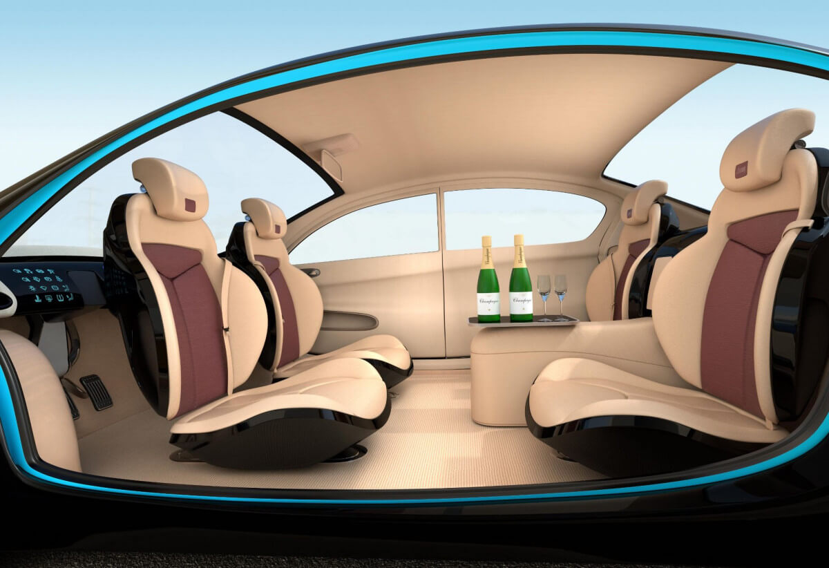
The interior of the vehicle can be redesigned to reach an ever higher level of comfort by masking the robotization as much as possible and by modifying the current car configurations.
How does the computer work ?
Generally, the computer of a driverless car runs on Linux. Linux is an OS (Operating System) highly appreciated by developers because it is powerful, always updated, and free. The wallpaper often looks like this.
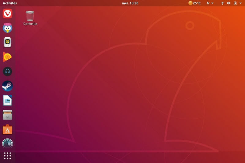
Coupled with this, ROS (Robot Operating System) is generally the tool installed to retranscribe the architecture of an autonomous vehicle and the communication of packets in real time.
The Software architecture
The software runs under ROS (Robot Operating System). It is a Linux-based system for managing the sending of messages in real time.
One of the great advantages of ROS is to allow bag recording. Record Bag allows you to record all sent messages and replay the scene later and test algorithms without having to return to the field. A bag file of a few seconds usually makes several Gb depending on the type of message that is sent.
ROS works as in the following diagram.
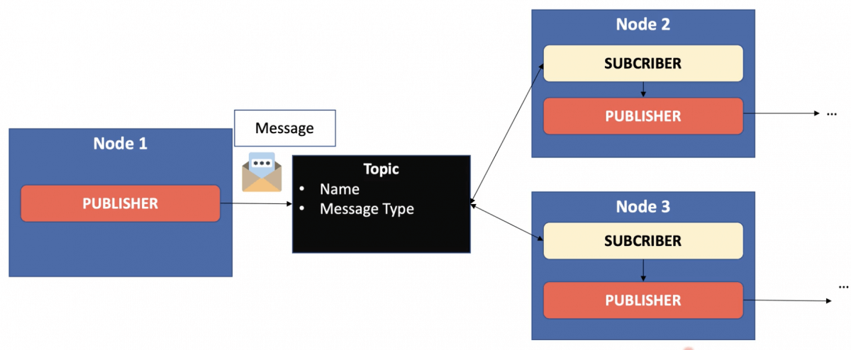
A ROS node is the equivalent of a function or a mini program. Its role is to publish information (obstacles, position, …) that we call messages. Each message is published on a topic.
A Node that publishes information is called a Publisher. Those who listen to and use this information are called Subscribers. Generally, a node is both Subscriber and Publisher. This architecture makes it possible not to block the system if a module does not respond. Nodes publish no matter if there are other nodes listening.
The set of nodes creates a graph.
What’s in a Self-Driving Car?
Introduction
The objective of a self-driving car is to operate a vehicle without a driver on a simulator and then in the real world. We could start by a parking lot.. The vehicle will have to drive several laps in the car park and stop in case of a red light.
There may be many sensors and components. Here’s an example architecture:
- RAM Memory— 31.4 GiB Memory
- Processor — Intel Core i7–6700K CPU @ 4 GHz x 8
- Graphic Card — TITAN X Graphics
- Architecture — 64-bit OS
This configuration allows for a fast processor speed. The graphics card and RAM make it possible to process images using Deep Learning algorithms. It was good for 2017, when I used it to drive on my first parking lot, but probably well outdated in 2021.
Architecture
Here’s the ROS Graph of all the nodes communicating together.
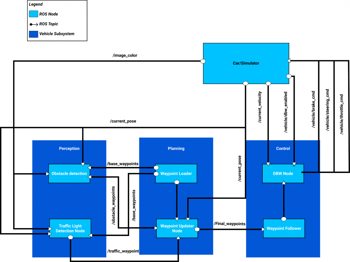
The architecture contains three subsystems (Perception, Planning, Control) as well as the vehicle. The vehicle publishes the camera image, the vehicle speed, the vehicle position (replacing the localization module) and a value indicating whether the autonomous mode is activated.
- Subsystems then have nodes.
- Waypoint Loader loads the waypoints that the vehicle will follow.
- Traffic Light Detection detects the color of the traffic lights.
- Waypoint Updater adapts the waypoints to the situation (red light).
- Drive By Wire calculates the steering angle, acceleration and brake values for the vehicle to take control if it indicates to be in autonomous mode.
These subsystems make it possible to drive the vehicle with a computer and to stop in the event of a red light. Many parameters already come into play. To operate on an open road, a vehicle must be more sophisticated to take into account the detection of the road, the traffic signs, the decision-making, the implementation of the highway code, the map …
Waypoints Loader Node
The trajectory is planned in advance, we know exactly where to go and do not need to calculate these points.If we already have a map, we can record the waypoints inside, containing the coordinates that the vehicle must follow.
What we communicate to other nodes is actually a line. A line is composed of waypoints. Each point is translated by coordinates (x, y), an orientation, the linear velocity and the angular velocity. This translates how the vehicle will roll.
The speed to adopt is the maximum speed allowed in the environment where we are. The points are then provided to allow acceleration and then maintenance at constant speed.
Traffic Light Detection
Red light detection is a Perception stage that develops in two stages.
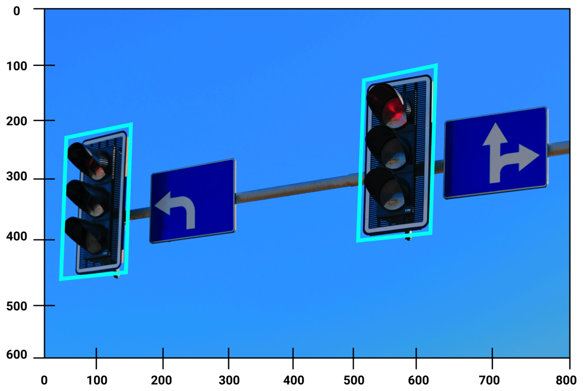
The first step is to train a model to recognize the lights and their color (red, orange, green). The chosen model is Faster RCNN and had to be trained on images of the simulator as well as on real images to be able to work in both cases.
Faster-RCNN is a model for detecting objects on images like YOLO (Single Look Once) or SSD (Single Shot Detector) are.
Once the training is finished, we are able to test our model and implement a node publishing position and state of the lights.
Final Waypoints Node
This step consists of modifying the points in case an obstacle or a red light is on our way. If we meet a red light, we will have to modify the points so that they stop at the level of the light. The car will have to decelerate in a smooth way for the driver.
How do we know the traffic light position ?
The position of the lights is given in the map, if we use one; or by the Perception system. In the case of the parking spot, we only had one light with a known position.
In the case where the position is unknown, SLAM algorithms and the use of LiDARs will accurately set the light.
Drive By Wire : Control
This last node calculates steering wheel angle, acceleration and brake using controllers like PID.
Results
On the video, we can see that the vehicle loads the waypoints that have been given to it with the Waypoint Loader node. If a red light is detected by the Traffic Light Detection node, the vehicle updates its waypoints using the Waypoint Updater node. Finally, the vehicle follows the waypoints through the Drive By Wire node.
In the video, the vehicle does not stop at a red light because of its low robustness to lighting. Although this is not a stalling point for the project, training should be better optimized and coupled with other detection systems such as V2I (vehicle to Infrastructure) for a production-ready version.
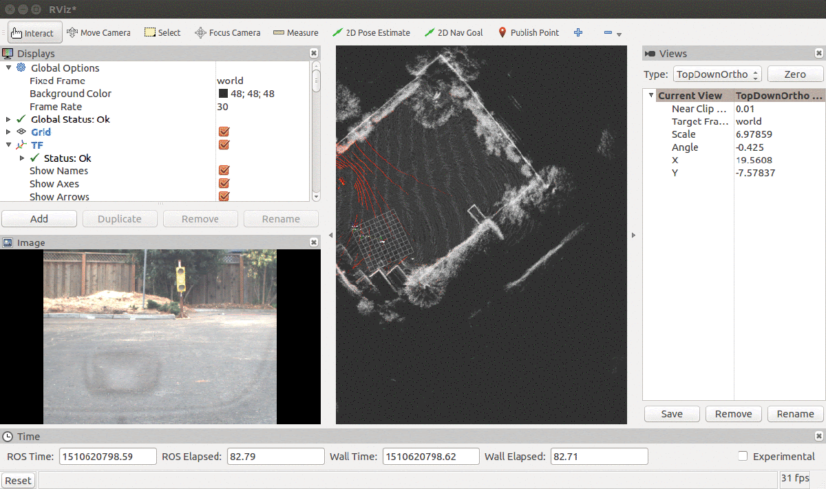
RViz tool can then display our results so we can work on it. On the left, we can see the camera image. On the right, the LiDAR output.
Conclusion
Congratulations on completing this series on Self-Driving Cars! You now know MUCH MORE about it than you used to. You know about the hardware, the software, and the core components.
If you’d like to keep learning, I invite you to join my daily emails and learn MUCH MORE about how to become a self-driving car engineer.
BONUS : You will receive The Self-Driving Cars Mindmap to download.


