Control Command for Self-Driving Cars

What is the meaning of Control algorithms in Self-Driving Cars?
This article on Control follows :
- Introduction to Computer Vision for Self-Driving Cars
- Sensor Fusion - LiDARs & RADARs in Self-Driving Cars
- Self-Driving Cars & Localization
- Path Planning for Self-Driving Cars
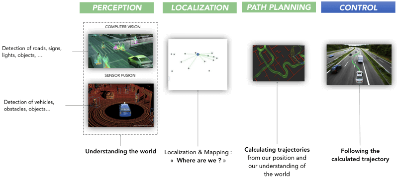
This is now the last step. An autonomous car uses the Perception module to know its environment, the Localization module to know its position in this environment and the Planning module to make decisions and generate trajectories.The Control module is now in charge of moving the vehicle by generating an angle for the steering wheel and an acceleration.

Waypoints
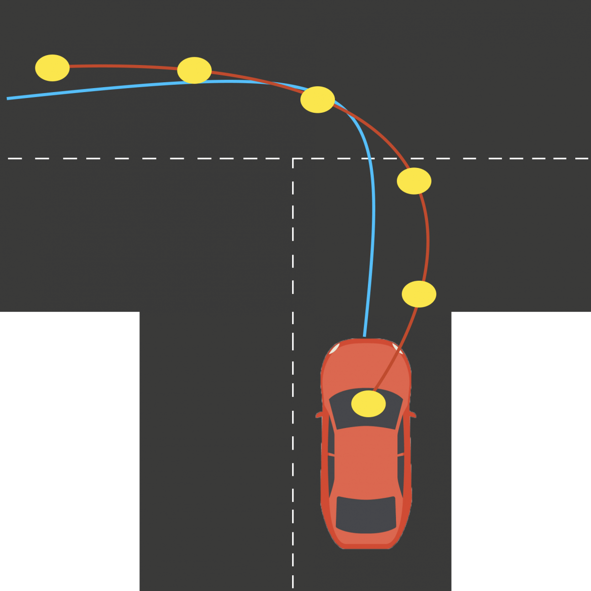
The Control step consists of following the trajectory generated as faithfully as possible. A path is a sequence of waypoints each containing a position (x; y) an angle (yaw) and a speed (v).
A Control algorithm is called a controller. The purpose of a controller is to generate instructions for the vehicle such as steering wheel angle or acceleration level taking into account the actual constraints (road, wind, wheel slip …) and the trajectory generated.

What Controllers ?
A large number of controllers exist to move a robot / vehicle. They are more or less complex depending on the problem that we want to solve.
PID — Proportional Integral Derivative
The simplest of all is called Proportional Integral Derivative or PID.
The PID controller is an algorithm that calculates a value (for example a steering wheel angle) from an error calculation. The error is the difference between the trajectory that we must adopt and the one we actually adopt.
We have three elements in a PID controller :
- P : Proportional — This term applies a correction to the steering wheel proportional to the error. If we are too far from the goal, we turn the wheel in the other direction.
The disadvantage of a single P Controller is that it causes a constant oscillation. Depending on the frequency at which the algorithm calculates the error, the oscillation is more or less important. The coefficient Kp indicates the degree of oscillation desired.
- D : Derivative — The purpose of the term D is to suppress this oscillation effect by adding a damping term to the formula. This term is the change of error. The PD controller understands that the error decreases and slightly reduces the angle it adopts to approach a smooth path.
- I : Integral — The last term is used to correct a mechanical error that causes us to turn the wheel more or less strong depending on the vehicle to stay upright. So we add a last term to penalize the sum of cumulative errors. The Twiddle PID curve corresponds to the use of an algorithm to find the coefficients more rapidly and thus to converge more quickly towards the reference trajectory.
We therefore have a sum of three components allowing the vehicle to follow a trajectory efficiently in real time. The different Kp, Ki, Kd are coefficients that we must find in order to optimize driving.
The PID controller is the simplest and most common in the world. It has the advantage of being implemented quickly and operating in simple situations. In the case of a stand-alone car, a PID controller can be used to calculate the angle and another to calculate the acceleration. Lateral and longitudinal controls are difficult to combine. Moreover, it is impossible to model the physics of the vehicle. When we drive, we naturally adjust our maneuvers according to the size, mass and dynamics of the vehicle. A PID controller can not do it.
MPC — Model Predictive Control
Other controllers are also known to integrate the physics of the vehicle (mass, size, …). They are more difficult to implement but more effective. These regulators can take into account the forces that apply to the vehicle, the characteristics of the vehicle, …
Actuators
We start by defining actuators. These are the elements to move the vehicle. A car has three actuators: a steering wheel, an accelerator pedal and a brake pedal . The objective of an MPC is to play on these actuators by varying the angle of the steering wheel, the pressure on the accelerator pedal or on the brake pedal.
Constraints and forces
We evolve in an environment called non-holonomic. This means that, for example, the wheels can not physically be at 90 °; they are rather between -30 ° and 30 °. Taking this into account makes it possible to have more realistic trajectories that are more faithful to the reference trajectory. We can also define acceleration as a value between -1 (braking) and 1 (maximum acceleration).
We also have two types of implementable models: kinematic and dynamic.
A kinematic model means that our vehicle realizes the implementation of mathematical formulas to define the movement and trajectory of the vehicle .
A dynamic model takes into account the fundamental principle of dynamics and therefore the forces applied to the vehicle. These forces can be the resistance of the air, the weight of the vehicle, thegravity, the contact of the wheels on the ground, … The centrifugal force can cause a vehicle to leave its trajectory in a bend and is not taken into account in a kinematic model.
Optimization
An MPC controller solves an optimization problem. Its purpose is to calculate several pairs (angle, acceleration) and choose the one that causes the lowest error.
MPC
The algorithm is as follows:
On the left, we calculate the current status via odometry, location, …
The Solver is then done in three parts:
- Constraints of the non-holonomic world
- Model (kinematic or dynamic) implementing state t + 1
- Cost is a formula calculating according to the state t + 1, the cost of the trajectory.
We can therefore test several combinations of angle, acceleration (δ, a). Each combination is associated with a cost. The algorithm then chooses the pair with the lowest cost.
Once the first actions are performed, we recalculate the future states and predict new angles.The MPC controller is very powerful but very difficult to implement. In general, the time spent developing this regulator is worth the result. An MPC controller can be very powerful and allow a vehicle to reach faster speeds while still being safe. Driving is more enjoyable than in a PID controller.
Results
As part of my Nanodegree on autonomous vehicles, I implemented two controllers to follow a trajectory: a PID regulator and an MPC regulator. The MPC regulator achieves higher speeds than the PID regulator (50 vs 30 mph) allowing a more pleasant and less oscillatory driving.
PID
MPC
Conclusion
In the world of robotics, there are a large number of controllers.
Depending on the type of robot you want to move, it can be more or less simple. The environment can also play a role. In an autonomous car, emergency braking may occur involving a more sophisticated controller than an indoor robot.
The Control stage is mandatory for robots and drones that we want to make autonomous. This step relies however on all the previous modules (Perception, Localization, Planning) which must be developed perfectly.
Controllers are difficult to export from one car to another since they are unique to a vehicle.
The five articles written around autonomous vehicles now cover all the stages of operation of a driverless car. The last project realized with Udacity in my nanodegree is the implementation of all these bricks in a real autonomous car running under ROS (Robot Operating System).
A final article on this subject will conclude this series.
📩To go further, I invite you to join my daily emails and learn how to become a self-driving car engineer by receiving daily career tips, learning the stories from the field, and get more technical content!

